Sunday, 25 October 2020

Sanyo RP 8880 Receiver

My dad bought this about 40 years ago, and I finally got around to making it work again in 2017. It is an interesting set, with "short wave" (HF) coverage from 2.3 MHz to 30 MHz (with a gap around 10.7 MHz for the IF) as well as the more conventional LW, MW FM and "marine band" (1.6 to 2.3 MHz). It's a pretty complicated radio with some unusual features.
 

 Removing the back cover reveals most of the workings:
 
 
I did find a service manual online, but the schematic required some cleaning up before I could follow it. I don't want to publish the entire thing for fear of breaching Sanyo's copyright, which is unfortunate.
 
In "short wave" mode, the signal path appears to be:
  • Antenna
  • Q106 RF amplifier
  • Pre-selectors L113 to L117 for SW1 to SW5 bands respectively.
  • Q107 & T103 mix to 10.7 MHz. Local oscillator is Q108.
  • Q109 10.7 MHz IF amplifier.
  • 10.7 MHz ceramic filters CF101 & CF102.
  • Q110 & T304 mix to 455 kHz. Local oscillator is Q111 & L120, adjustable by bandspread (VC4).
  • Q302 & Q303 455 kHz IF gain.
  • CF302 & CF303 if "narrow" selected.
  • Q305 & T305 455 kHz IF gain.
  • D307 drives the AGC & D308 detects the audio.

 Issues Found

  1. Dirty switches. A squirt of contact cleaner and some exercise solved this issue.
  2. FM band was dead. This turned out to be Q103 (2SC930D), the local oscillator transistor. This had insufficient gain and was replaced with a SS9018G. Realignment of the oscillator was then required.
  3. I also replaced Q108, another 2SC930D functioning as the short wave local oscillator. This required realignment of all five bands.
  4. The ceramic filters seem to have drifted over time. This requires that the IF is aligned to this new frequency. I should have realised this before aligning the oscillators as I had to do that again!
  5. The bandwidth of the FM IF is too narrow for good reception. This is due to the ceramic resonators used. The radio shares some IF stages in different bands, so compromises are inevitable.
  6. The "SW5" band (20 to 30 MHz) is very sensitive to the position of the band select switch. Switch cleaner did not improve this, and I am reluctant to try to dismantle the switch for fear of doing more harm than good.


Low Gain 2SC930D Transistors

It would appear that the 2SC930D transistors used in this and other receivers lose their gain over time. I had not encountered this before. I replaced some of them and measured the gains of those I removed.
 
Q303 2sc930d gain measured at 31.
Q302 2sc930e gain measured at 34.
Q305 2sc930d gain measured at 33.

Q302 was replaced with a BC550CBU, the others with SS9018G. A 2sc930e should have a gain of 100 to 200. The BC550CBU I used measured over 500!
 

Ceramic Filter Drift

The manual gives two figures for the 2nd IF centre frequency: 455 KHz and 460 KHz depending on where you look. I think it is more likely to be 455 KHz as this is more common. I found the centre frequency of the ceramic filters to be 472.5 kHz, and I adjusted the second IF to that. This is 3.74% error, well out of the specifications that I found, ±0.5% plus ±0.3% ageing over 10 years typically. But then this receiver is about 40 years old! Elsewhere in the manual (the front cover and the resonator part number on the schematic) is suggests the 2nd IF is 460 kHz. In this case, the error is 2.61%. In either case there is a significant error.
 

Using An Even Older Signal Generator!

Using my ancient AVO Mk. 3 signal generator (right) to align the IF stages. This piece of equipment is much older than the radio - so old it has a valve in it! It works well though, so I am inclined to keep using it.


Conclusion

Having spent a huge amount of time on this set, it feels like time to call it a day. All bands work and are about as aligned as I can make it. Outstanding issues are:
  1. The signal strength meter reads very low on the FM band. I think this has been an issue from new, as the corresponding preset was set at the maximum setting.
  2. The "Band Spread" dial calibration is poor. It is fine around zero, but is progressively inaccurate as the frequency is increased. Generally, the band spread feature doesn't seem that useful anyway. Attempting to correct this with the relevant oscillator tuned circuit results in running out of capacitance adjustment range.
  3. Something is wrong with the BFO circuit as attempting to align this according to the manual reveals a tuned circuit with no effect. However, SSB signals can be heard well enough so I didn't pursue it.
  4. I have no good way of measuring the sensitivity, but suspect that it isn't as good as suggested in the manual. It would be interesting to try it with a calibrated source of some sort.
 

Roberts R200 AM Radio

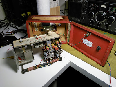
In about 2011, I was given an old transistor radio. It certainly hadn't been used for many years, and I thought it might be interesting to breathe some life into it. It is a very basic set - just medium and long wave, but is old enough to be interesting. I think it dates from about 1962, and as such is from the early years of transistor radios. It uses germanium transistors. The audio output stage is transformer coupled, which is a feature of most valve designs that preceded it.

A simple catch allows the back cover to be opened.

I found a service manual for it online (£1.99 from http://www.service-data.com) which was very helpful as it includes the schematic and alignment instructions. Rather to my surprise, the radio worked as soon as power was supplied, but unfortunately not very well. It was rather insensitive and the tuning scale was inaccurate.

Removing the chassis was straightforward and allowed a general clean-up of the scale and other parts that are not normally accessible. The set does not appear to have been worked on previously, which is good to see.


Following the alignment procedure is a good way of finding issues with a radio if you have the equipment and the patience. In this case, the alignment was pretty close with the exception of the preselection filter. These are tuned by moving the coils on the antenna ferrite rod. Unfortunately, the coils had become loose with age moved from their proper position. This was the main cause of the insensitivity.

Another issue was that the ferrite cores are held in the IF transformers by small pieces of what I imagine was once elastic. I had to replace these to enable the cores to be adjusted without them falling completely though the coil! This (right) is the inside of one of the transformers.

On the whole, the radio works about as well as I would expect for such a comparatively simple radio. Contrary to popular opinion, the electrolytic capacitors still work, at least well enough to perform their intended functions. Don't believe everything you read about old capacitors!

This radio is now in semi-regular use in my living room. Reception on the internal rod is tolerable, though it does perform much better when connected to the long-wire antenna I have run down the garden!


The Demise of a BT Home Hub 4

During a severe storm with flooding in my area in June 2016, my telephone line and ADSL (internet) modem were damaged. The line measured a direct short-circuit and was duly fixed by the telecoms company (BT). The modem appeared completely dead, and I discovered that it rattled when I shook it. That can't be good!

Removing the cover revealed a single PCB:

There are a few components on the underside:


The telephone line is connected to a gas discharge tube (GDT) and two large capacitors. The capacitors have both exploded, and fragments of the cases were the source of the rattle.


 Here is a close-up view:

Up to this point, I thought perhaps there may be a chance of repairing the modem. Unfortunately, a closer look revealed more damage.


The GDT is connected across the line, so would have done nothing to protect the electronics from a common-mode signal (i.e. one appearing on both lines). I suspect that a nearby lightning strike induced an energetic pulse in the line and caused the damage to the modem. It also probably damaged the electronics at the other end of the line, which is why the line was short-circuited.

I did take some photographs of the other major semiconductors in the modem.

The Broadcom BCM63168 is a "xDSL Integrated Access Device SoC", so would appear to contain the bulk of the modem itself plus the processor. The processor is a 400MHz dual-core MIPS CPU. Link to Broadcom site: bcm63168

The is a 64M x 16-bit  DDR3 Synchronous DRAM (SDRAM):


Broadcom B50612E Ethernet PHY:

Wireless (WiFi) interface:


Popular Posts